UPDATE 2021-01-02 – I’ve created a repo with the datasheet for the main encoder (and other MStar chips) at https://blog.obsoletemadness.com/2021/01/02/mstar-datasheets/
I recently purchased a couple of cheap SCART to HDMI adapters from AliExpress. The first one I ordered claimed it could do both 50 and 60hz output. Unfortunately, it didn’t have a button to do the toggle and after a prolonged fight with the vendor I got a refund.
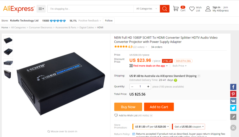
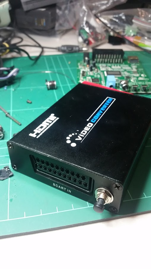
So I tried a different model. This one clearly had a PAL/NTSC button on it. (As an aside, while today the price difference between the two models is about $1, when I originally ordered these, the second one was almost $20 dearer).

Sadly, while this one could output 720/1080p@50hz it would corrupt the display after 30 seconds. Rather than be stuck with two adapters that didn’t work the way I needed, I decided to see if I could add a PAL/NTSC button to the one that did work!
Looking at the two devices it was clear that one was simply a cost reduced version of the other (at the time I bought them, there was nearly a $20 difference, it looks like they’ve come down a bit since).

So, I traced where SW2 on my broken board. SW2 goes directly to whatever pin this is on this unknown chip.

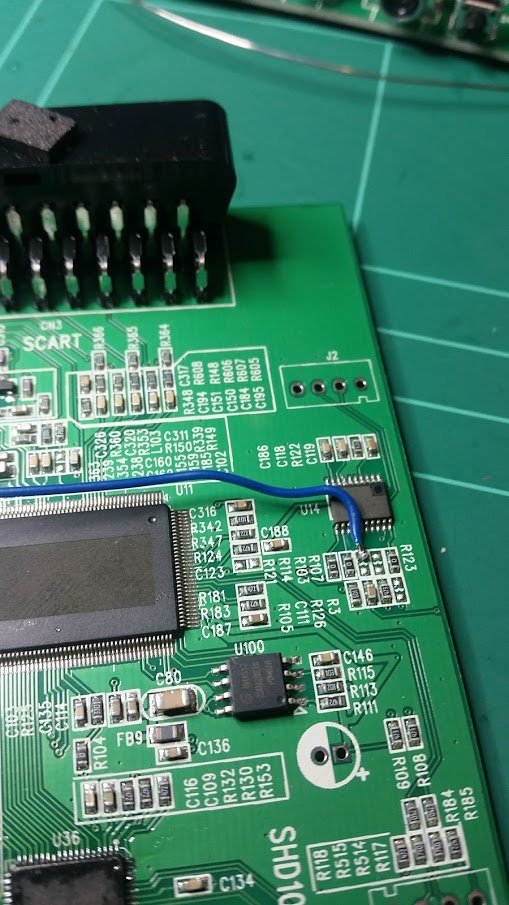
The way I did this was to wire one end of a switch to the unpopulated R103 pad closest to U14. I then wired the other end of the switch to ground via a 470 ohm resistor.
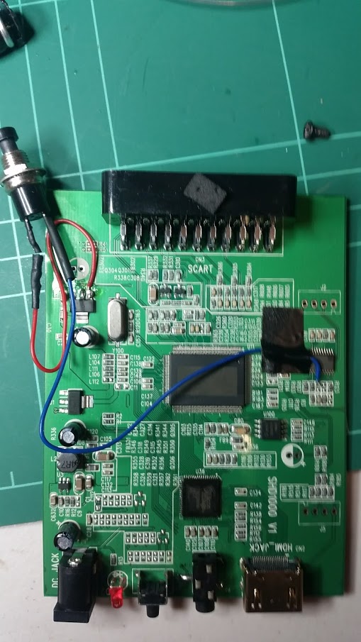
Finally I drilled a 6.5mm hole in the front SCART connector face of the case and pushed the switch through.
Behold! 50hz output!

Is this worth it? Only if you already have the adapter without the PAL/NTSC toggle. If you’re buying one the price difference between the two devices is only $1 now – and the one with the toggle has HDMI input, and Coax digital out.
A quick review
These boards do what they promise, they convert SCART (including RGB) to HDMI at various output resolutions. The video quality on them is quite good – and they’ve worked with everything I’ve tried (C64, Amiga RGB, Sega Megadrive, SNES). The usual caveats apply for progressive 240p-ish sources. There is a de-interlacing filter on them that bobs the image slightly.
Future Mods
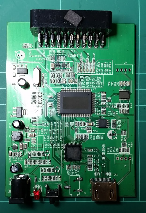
I need to find out what the two unknown chips are on the board (U11 and U14). U14 is clearly a micro of some description, handling the button presses, etc. U11 looks like an LCD TV SoC (which makes sense). But what one? The headers for what I think is the ISP are quite clear – so perhaps there’s an opportunity to (say) disable the de-interlacing.

Do you know if there is a way to influence the output aspect ratio in these? Currently they seem to stretch the 4:3 input to something that looks 16:9, but off-center and with some black bars. I would like to control it.
Nope I don’t sorry. If I had the tools I’d try and dump the program of the little micro on the board. I haven’t found a datasheet on the main chip though so not sure how useful it would be anyway.
I have a SHD1000 V1 just like what you’re working on. I loved it for the two times it worked but now I no longer get any signal from it. It turns on and my tv acts like it sees signal but nothing is there. Do you have any information on how I can troubleshoot what may have failed? As far as I can tell, everything on the board looks clean and in normal condition.
Not really sorry. I find they run hot (especially the main ic and HDMI transmitter) and don’t usually come with any heatsinking. As such I’ve got one that cooked itself. If you order another grab some cheap heatsinks to go with it.
Really late, but I have the big one without blacked out chips. U11 is a mst6m182xst-z1 and U14 is a 8s003f3p6
Thanks! So just an stm8 … Might have to see if I can dump the fw
I’d love a proper data sheet/programming manual for the mst6m182 if anyone knows of one?
Hard to find online… it’s possible to find schematics that use this chip though, so we can get the pinout:https://www.520101.com/html/mappaper/tclpaper/200153566.html
Seems some datasheet exist behind paywalls…https://download.csdn.net/download/zhouke58/7982775
I tried to ask Mstar for a datasheet of another chip some time ago but the mail bounced… They got bought by MediaTek at some point, but their contact form didn’t really get me any answer either.
I couldn’t get hold of the one you linked but this is similar. The programming registers was what I was really after, especially for handling de-interlacing:
Click to access mst6m48rvs_ds_v02_for-shiyuan.pdf
EDIT: Found it!
Click to access mst6m182vg_v05.pdf
Cool, any place I should look for tsumv53ruul-z1 datasheets? 😉
I’d try http://en.pudn.com/
If you find it I’d love a pull request to https://github.com/ObsoleteMadness/MSTAR_Datasheets
Hello, I have one same of you. The problem is the image is shift to right of screen. Please , you can dump the CI u100 ( spi 4mb) and share for test? thank you.
I don’t have the tools to do that…unless you can point me to an Arduino project or the like to dump the contents?
Good Morning.
To dump the spi I used the ft232 and mstar spitool and connected it to the J5 of the scart board. Stm8s003 has no way to dump eeprom as it is read protected.
I tried to read it and ended up erasing his memory and the scart doesn’t care anymore.
I need the copy of the SPI J5 from the smaller scart. If u can help I appreciate it.
Finaly… Chinese scart hacked. https://www.youtube.com/watch?v=DvsWq2OgA5k&t
Nice! Did you find a programming manual mst6m182?
[…] previously blogged about Chinese SCART adaptors. These are very low cost adaptors which convert RGB SCART to HDMI, with two main variations based […]
I’ve got a later revision of the model with the SPDIF out and the markings on the chips haven’t been etched off, so I thought I’d post them here (I know most have been posted, I’m just being thorough):
Main encoder IC: MST6M182XST-Z1 (MStar)
HDMI transmitter: SIL9022ACNU (Lattice)
U14 (MCU): STM8S003F3 (STMicroelectronics)
U100 (SPI flash): 25Q32JVSIQ (Winbond)
Nice. So you have a picture of the board?
Sure, sorry for the wait, I took a bunch because my camera is quite possibly the worst on a modern phone, here’s a link:
https://drive.google.com/drive/folders/1NTV3vQP_NDeqZsHVGasu3F0a1t5WfcCp?usp=sharing
I think the only real change is component arrangment and the two voltage regulators replaced with three A10A’s coupled with inductors.
That’s great. Thanks for that. Indeed its close to another version I have.
Btw, I just ordered one of these (the one with HDMI in), and it works… except with the HDMI USB capture device I also got… I thought it didn’t work, but it does with another source. Very useful.
I thought it could be some hotplug detect issue but the Sil9022 output driver should detect it as low as 1.9V, and it’s around 3V…
For the record, I managed to get it to work by forcing the hotplug detect signal internally…
I also modded it to force RGB input to save one power brick. I tried to force 4:3 as well but it doesn’t work. I’m quite sure I’ve seen it handle it once or twice before, maybe I burnt the input pin or something, now it has like 3.3V regardless if there’s anything on it…
(4:3 is supposedly detected when pin8 on SCART is >9V, and here there’s a resustor divisor (10k and 2.2k) which should get about 2V on pin 141 if I didn’t misscount.)
Oh, and the uC on mine is an ST 8S003F3P6 it seems.
The unpopulated header next to it seems to be: GND, SWIM debug, NRST (reset) and 3.3V.
And the other header that goes to the main chip seems to be a USB interface, but probably host, plugging into a computer doesn’t do anything.
I’m not sure it’s USB. There’s a heap of Mstar programmers on AliExpress and a few flashing tools floating around online. I’ll need to check the spec sheet to see what protocol it uses.
The 4 pin header is rs232.
I accidentally connected 12v. Fried a transistor near the power connector. Would you be able to tell which traffic is marked as U3?
U3: M3406-ADJ
I repaired the 0.6 volt power supply after I connected 12 volts. Replaced U3.
But MST6M182XST-Z1 is no longer active.
Only STM8S003F3 works, even downloaded the firmware.
Hello, You can share de firmware for STM8S003F3?
I made a mistake.
After U3, the voltage is 1.3v. I just have a resistor R16(40.2kOm) in the open.
0.6*(1+(47k/40.2k)) = 1.3V
Fixed and earned 25Q32JVSIQ, MST6M182XST but SIL9022ACNU does not work, it needs to be changed.
STM8S003F3 it is only 3 button keyboard (slave i2c ) and storage for serial number
I have programed the stm8s to slave address 20, inserted EDID e scart bootup and enter in BUG after 10 minutes. I believe the driver register for SIL9022ACNU is needed in code. I working on Stm8s glitch do bypass R.O.P in stm8s and dump the full code.
I upload dump in github_com/OlegDX/SCART_HD_HDMI.
And also disassembled the firmware , everything was written as before
I have dumped my EDID and eeprom in data logger, The EDID is the same as your dump the eeprom not. I try to edit yout dump with my eeprom and not boot up the crc of eeprom is FE.
Thank you, Thank you, After insert the serial in STM8S DUMP, this boot up my dead scart !
Thank you !!!!!!!!! How you dump stm8s ?
I have flashed stm8 and not boot up, how to insert serial in eeprom?